Production and Manufacturing
Production and manufacturing overview
1 Material selection
The development of food packaging requires a synergy between mechanical functionality, chemical stability, and environmental sustainability. In accordance with the Design in Plastics (DiP) principles, the selection of materials is driven by the hierarchy of the "Plastics Performance Pyramid." The high volume associated with food packaging necessitates the use of commodity plastics to maintain economic profitability, generally excluding high-performance polymers. Engineering polymers may be considered only if their enhanced properties, such as superior gas barriers, justify the increased cost.
A fundamental constraint for this assembly is that both components must be suitable for injection molding. While the cap is a direct injection-molded part, the bottle involves a two-stage process: the polymer is first injection molded into a preform and subsequently stretch-blow molded into its final geometry. This report evaluates the molecular architecture and macroscopic properties of potential polymers to justify a final material selection.
The Squeezable Bottle
The bottle serves as the primary containment and dispensing unit. To establish the parameters for material selection, one must first evaluate its functional requirements and environmental context. The primary mechanical requirement is the capacity for high elastic deformation during dispensing. The bottle must withstand a typical manual squeezing force of approximately 20–40 N without permanent deformation, requiring a material with an equivalent stiffness (Young's Modulus) in the range of 0.2–0.5 GPa. Secondary requirements include high chemical resistance to the acetic acid in ketchup, low oxygen permeability to prevent oxidation, and transparency for consumer appeal. The bottle must maintain these properties across a temperature range of 4°C (refrigeration) to 40°C (transport and storage).
A prominent candidate is Low-Density Polyethylene (LDPE), a branched polymer where long-chain branches disrupt molecular packing. This architecture reduces the degree of crystallinity, leading to a lower density and a low Young's Modulus, which facilitates the required "squeeze" functionality. The weak van der Waals intermolecular forces between the non-polar chains allow for easy chain sliding and high flexibility. Conversely, High-Density Polyethylene (HDPE) possesses a linear molecular structure with minimal branching, allowing for high crystallinity (>70%). While this increases the moisture barrier, a desirable trait for food packaging, it also increases stiffness beyond the threshold for optimal squeezability.
Polypropylene (PP) is another candidate with relatively low stiffness and a small methyl (−CH₃) functional side group. While PP is chemically inert due to the absence of polar group interactions or hydrogen bonding, its glass transition temperature (Tg ≈ 0°C) is significantly higher than that of PE, potentially leading to brittle failure if the packaging is dropped under refrigerated conditions. To identify materials with enhanced chemical and barrier resistance, polymers with polar side groups must be examined.
Polyethylene Terephthalate (PET) contains rigid aromatic rings in its backbone, which significantly restrict chain mobility. These bulky rings contribute to the material's rigidity. This results in high transparency and an excellent gas barrier. While it is an optimal choice for preservation, its high stiffness typically makes it less suitable for a squeezable design. A more flexible alternative is Ethylene Vinyl Acetate (EVA), a copolymer that introduces polar acetate side groups to disrupt polyethylene crystallinity. While EVA exhibits good gas barrier properties and extreme flexibility, its lower thermal stability makes it less favorable for food contact than pure polyolefins.
The two most viable options are LDPE and PET. From the perspective of ergonomic accessibility for users with reduced grip strength, LDPE is a strong candidate due to its lower stiffness and weak van der Waals forces. However, food safety regulations and quality standards necessitate a robust oxygen barrier to prevent the ketchup from browning. PET provides this barrier through its rigid aromatic rings, which decrease the "free volume" available for oxygen permeation. Furthermore, PET is an amorphous material that minimizes light diffraction, resulting in the optical transparency essential for consumer appeal. Consequently, PET is selected as the most suitable polymer for the bottle.
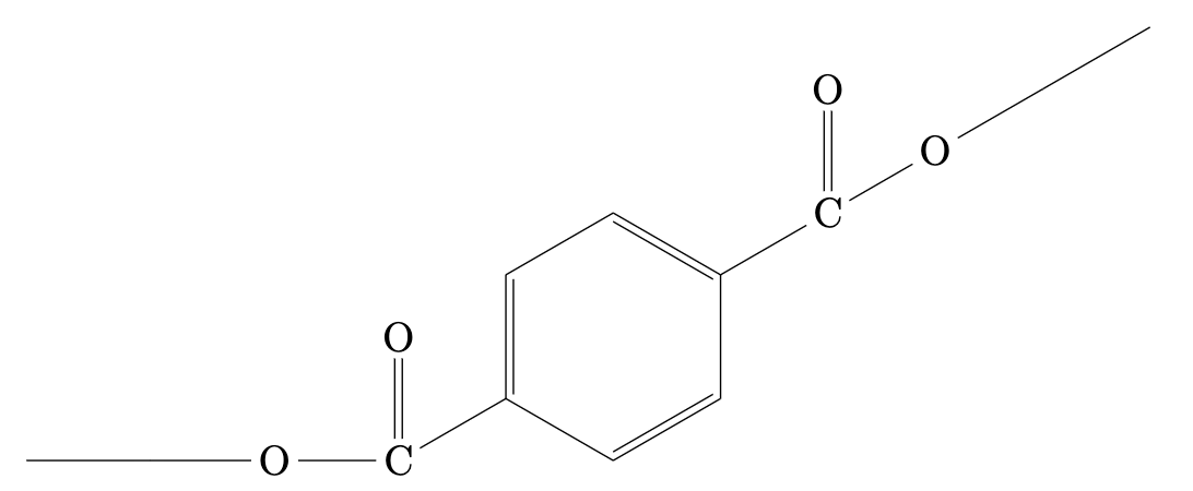
Figure 1: Molecular structure of PET
The Functional Cap
The cap requires high dimensional stability to maintain a constant thread pitch and high fatigue resistance for the integrated living hinge. The closure must provide a hermetic seal through a screw-thread assembly and withstand repeated bending cycles. Additionally, the cap is subjected to significant torque during assembly and must be sufficiently stiff to resist deformation.
Polyamide (PA) features polar amide (−CONH−) groups that form strong intermolecular hydrogen bonds, providing the excellent mechanical strength required for a cap. However, PA is hygroscopic; the absorption of moisture from the ketchup or environment would cause dimensional swelling and potential leakage, rendering it unsuitable for this application. Polycarbonate (PC) is an amorphous engineering plastic characterized by bulky aromatic rings. While PC is highly rigid and dimensionally stable, resulting from intermolecular bonds such as π-π stacking and dipole-dipole forces, it is susceptible to crack propagation when in contact with oils and fats, which disrupt these secondary bonds.
Polystyrene (PS) also offers dimensional stability but possesses a high Tg, making it too brittle at room temperature to withstand functional loads. Acrylonitrile Butadiene Styrene (ABS) provides a tougher alternative; however, its amorphous microstructure is susceptible to crack propagation over the numerous cycles required by a living hinge. Semi-crystalline polymers, such as Polypropylene (PP), manage these stresses more effectively because their crystalline regions act as reinforcing domains that restrict chain motion and increase the elastic modulus.
Polypropylene's advantage lies in its semi-crystalline morphology and its isotactic methyl (−CH₃) side groups. When a PP hinge is flexed for the first time, the crystalline lamellae orient themselves in the direction of the applied stress. This is called intralamellar slip and happens above the glass transition temperature Tg; the molecular alignment creates a highly tough bridge capable of withstanding thousands of opening cycles without crack propagation. Due to this specific structure-property relationship, PP is the industry standard for functional closures and is selected for the cap design.
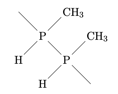
Figure 2: Molecular structure of PP
2 Cantilever snap fit mechanical analysis
The cantilever snap-fit mechanism represents a highly efficient assembly method for securing bottle lids. Snap-fits are integral design features that leverage the inherent elasticity of polymer materials to create secure, functional joints. The primary advantages of snap-fits include economic efficiency, sustainable "Green" design, and functional versatility. Such features can be molded directly into a component, requiring no additional cycle time or secondary hardware. Furthermore, by eliminating the need for adhesives and metal fasteners, the assembly remains monomaterial, which facilitates direct granulation and recycling without manual dismantling. Cantilever snap-fits also offer the design flexibility of either permanent or releasable joints.
The performance of a cantilever snap-fit is governed by the relationship between material properties and geometric constraints. A successful design requires translating a desired output, such as a specific opening force, into precise input variables. Regarding material selection, the specified constraint is Polypropylene (PP). For repeated applications, the allowable strain is approximately 4%. If a joint is intended for single-use, this strain limit can effectively be doubled.
| Material | Young's Modulus (E) | Allowable strain (ϵ) | Coefficient of friction (µ) |
|---|---|---|---|
| Polypropylene (PP) | 1,574 GPa | 0.04 | 0.3 |
The remaining input variables are dimensional and can be engineered to achieve the target output. In the case of a bottle cap, the desired output is the force (W) required to engage and disengage the cap. To ensure ergonomic operation for the user, a closing force of 5N is targetted, while an opening force of 15N is required. The opening force is intentionally higher to prevent accidental discharge or opening. The length, width, and thickness of the cantilever beam are governed by the dimensional constraints of the cap and standard design principles for polymer molding. The engagement and release angles can be adjusted freely to meet these requirements.
- Length (l): 7 mm
- Width (w): 10 mm
- Thickness (t): 0.8 mm
Maximum Deflection
Using the formula for cantilevers with a constant cross-section, the maximum deflection is determined as follows:
y = ϵ · l² / (1.5 · t) = 0.04 · 7² / (1.5 · 0.8) = 2.45 / 1.2 ≈ 1.63 mm
This equation assumes that only the snap hook undergoes flexion. In many practical applications, the molding face to which the hook is attached will also flex slightly; this occurrence can be regarded as a inherent safety factor.
Force Calculations
The force orthogonal to the beam required to deflect the cantilever by y is given by:
P = wt² · Eϵ / 6l = E · wt³ · y / 4l³ = 1574 · 10 · 0.8³ · 1.63 / (4 · 7³) ≈ 9.54 N
The force required to engage or release the fit (W) is the primary output variable affecting user experience. This force is a function of the normal force (P) required to deflect the arm and the geometric angles (α) and (β) of the hook faces:
W = P · (µ + tan(α)) / (1 − µ tan(α))
Required Angles
Since a specific output force (W) has been defined, the formula is inverted to solve for the required angle:
α = arctan((W − µP) / (P + µW))
For the bottle closure, an engagement force of 5 N is desired:
α = arctan((5 − (0.3 · 9.54)) / (9.54 + (0.3 · 5))) ≈ 11.0°
For the release mechanism, an opening force of 15 N is required:
β = arctan((15 − (0.3 · 9.54)) / (9.54 + (0.3 · 15))) ≈ 40.8°
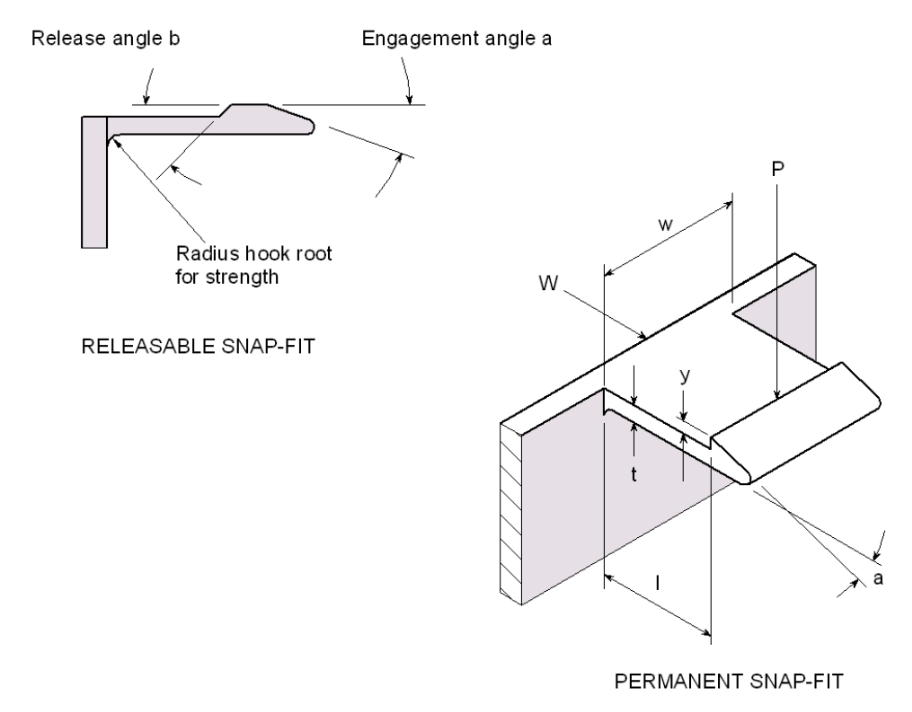
Figure 3: Cantilever snap-fit diagram
3 Manufacturing and mechanical analysis of the bottle preform
The bottle production involves a two-stage process: the polymer is first injection molded into a preform and subsequently stretch-blow molded into its final form. To ensure the preform is production-ready, specific CAD parameters were implemented:
- Wall Thickness: A constant thickness of 3.1 mm ensures uniform cooling and prevents sink marks.
- Draft Angle: A 1° draft angle was applied to the body to allow the part to eject from the steel mold without friction damage.
- Final Thickness: The wall thickness is reduced to 0.4 mm in the final blown bottle.
Stretch Ratio and Height Calculations
SR_total = SR_h × SR_a = 7.5
h_preform = h_f × SR_total = 3.1 mm
To ensure structural integrity during high-pressure blowing, we utilized precise geometric formulas. An internal radius of 1.86 mm (0.6 × h) was set to eliminate stress concentration points. To maintain a constant wall thickness of 3.1 mm through curves, the external radius was set to 4.96 mm (r + h).
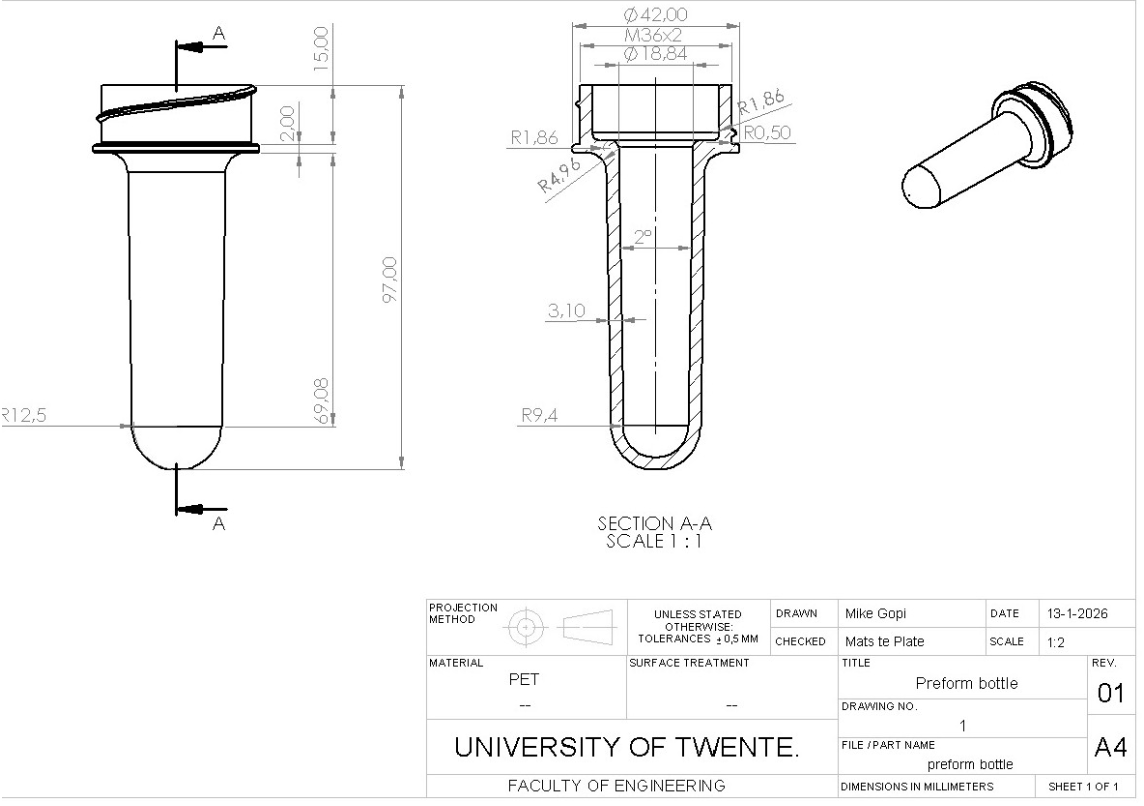
Figure 4: Technical drawing preform
Industrial Implementation
This design is highly feasible for Heinz. The process utilizes existing injection molding and stretch-blow molding infrastructure. Implementation requires only a new mold cavity and an updated labeling machine. Since the material remains consistent with current PET usage, the design carries low technical risk.
Force Calculations
The preform must act as a temporary pressure vessel. During production, it is subjected to an internal blast of 40 bar (4 MPa). We verified the 3.1 mm wall thickness using the following mechanical formulas:
Stress Analysis:
- Longitudinal Stress (σl): σl = P × D / (2 × t) = 8.05 MPa
- Hoop Stress (σh): σh = P × D / t = 16.1 MPa
Clamping Forces (Fc):
- Injection Stage: Fc(injection) = Ap × P = 150 kN
- Blowing Stage: Fc(blow) = A_bottle × P_blowing = 60 kN
With the yield strength of PET ranging from 50 to 80 MPa, this design maintains a safety factor of over 3.0. This ensures the preform expands plastically without bursting. The blowing machine must provide a clamping force exceeding 60 kN to prevent visible seam lines.
Buckling and Top Load Resistance
While the 0.40 mm sidewall is optimized for squeezability, it must withstand palletization loads.
This confirms a top load resistance of 1.9 kN, ensuring structural stability during storage and transport.
4 Technical specifications of the bottle Cap
The bottle cap production consists out of an injection molding process. To ensure that the bottle cap is dimensionally stable and to maintain manufacturing efficiency, a few design rules have to be applied.
Draft angles
Draft angles are essential in injection molding to facilitate part removal. Without a slight taper, typically between 1.5° and 3.0°, the plastic creates a vacuum or generates high friction against the mold walls during cooling. This leads to surface scuffing, part warping, or total ejection failure, compromising both aesthetics and production speed. In this design a draft angle of 3.0° is chosen.
Wall Thickness
Maintaining a uniform wall thickness of between 0.5mm and 4mm is vital for structural integrity and aesthetic quality. Consistent walls ensure the polypropylene cools evenly during the injection molding process, preventing internal stresses and "sink marks", depressions caused by uneven shrinkage in thicker areas. Too thin walls may result in solidification of the plastic because of rapid cooling before the molten plastic completely fills the mold. Too thick walls will result in sink marks in the solidified parts. A difference in cooling rate then causes internal stresses and finally warpage, causing the part to twist and deform. In the lid part of the cap a wall thickness of 2mm is chosen, this part must have a higher stiffness to ensure the continuous operation of the snap-fit mechanism within. For the rest of the cap a wall thickness of 1mm is chosen, for faster manufacturing.
Living hinge
Designing a living hinge requires precise geometry to ensure longevity. Key rules include maintaining a thin cross-section between 0.25mm and 0.50mm to allow molecular alignment. The length of the living hinge in its fully opened position is 1.5mm. Incorporating generous radii at attachment points prevents stress concentration, while ensuring the plastic flow is perpendicular to the hinge line prevents premature tearing during repeated use.
Additional Specifications
The thread of the bottlecap is a standard M36x2 ISO measure to fit nicely with the preform. To further prevent any warpage or sink marks, any ribs or bosses have a wall thickness of 50%-60% of the original wall thickness. The radii of all corners are larger than 0.125mm to prevent stress concentration. A grip patch around the edge of the bottle provides extra grip needed to provide the necessary torque for unscrewing the cap.
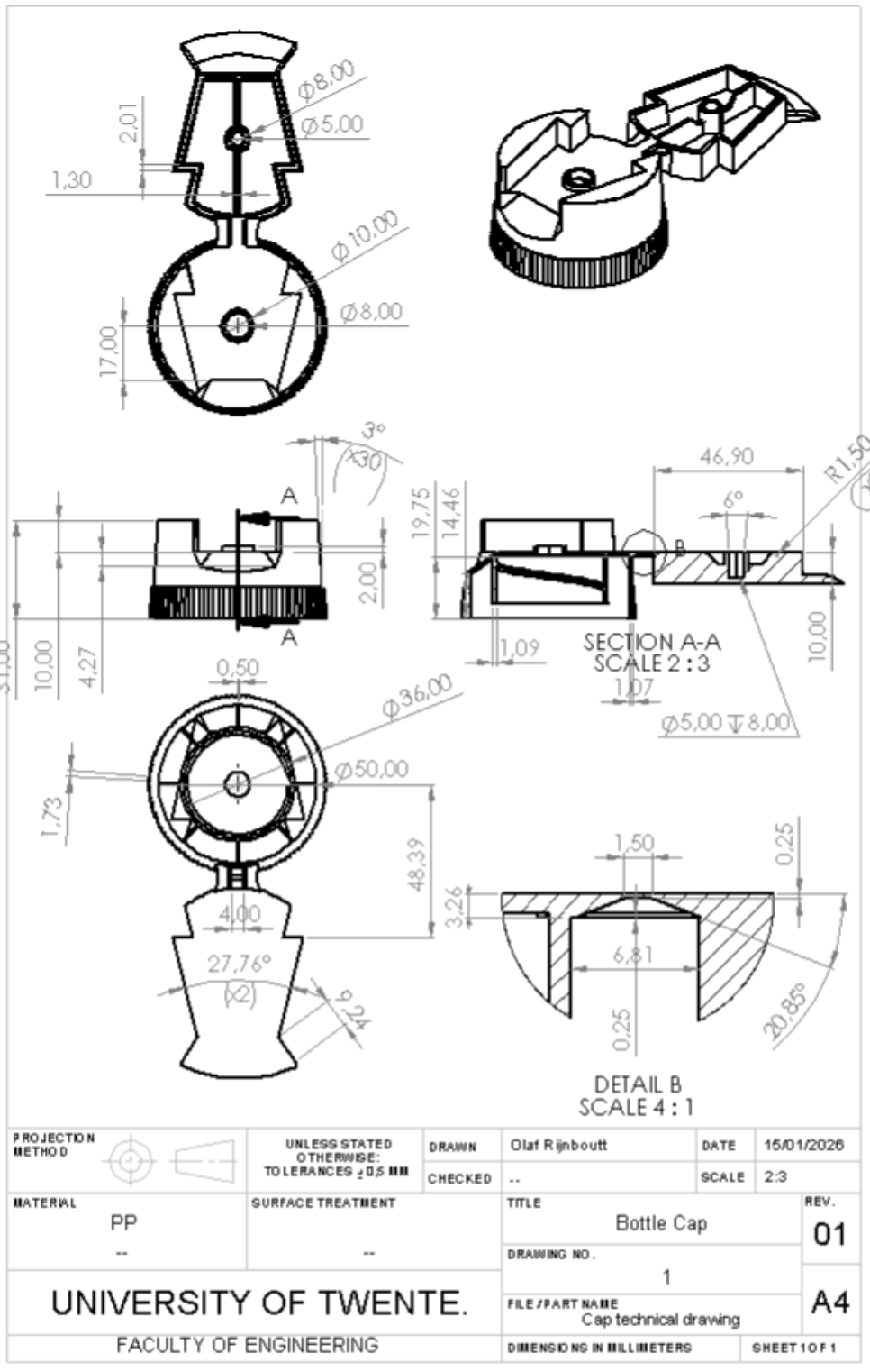
Figure 5: Technical drawing bottle cap
5 Injection Mold Analysis
While designing the cap, the ability for it to be injection molded had to be kept in mind. By making the product hollow, the shrinkage after injection molding will be relatively low.
A choice had to be made to use one or two injection gates. With one gate, there will be less weld lines, and a less costly machine will be needed. With two gates, a more expensive machine will be needed, but there will be significantly less shrinkage. This will result in higher quality product output.
A two-gate system was chosen, as this resulted in significant improvement in volumetric shrinkage and warpage. It also slightly reduced the fill time, allowing for higher output.
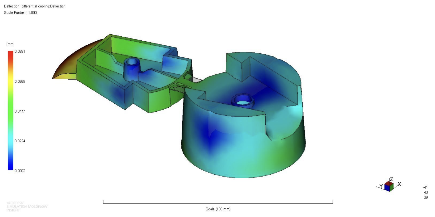
A cooling system was designed that further reduced the warpage effect, since warpage in a precise part like a cap, requiring a tight tolerance to prevent leakage, was needed. This cooling system consisted of cooling channels in the metal mold. By placing these channels at critical locations, the part is cooled more evenly and shrinkage is reduced. A combination of cooling channels as well as a baffle that goes up into the center of the cap was designed. This design requires minimal machining in the mold while providing adequate cooling to the part. Warpage due to differential cooling was reduced to less than 0.1mm, which is a substantial improvement from the original, non-cooled value of over 0.15mm.
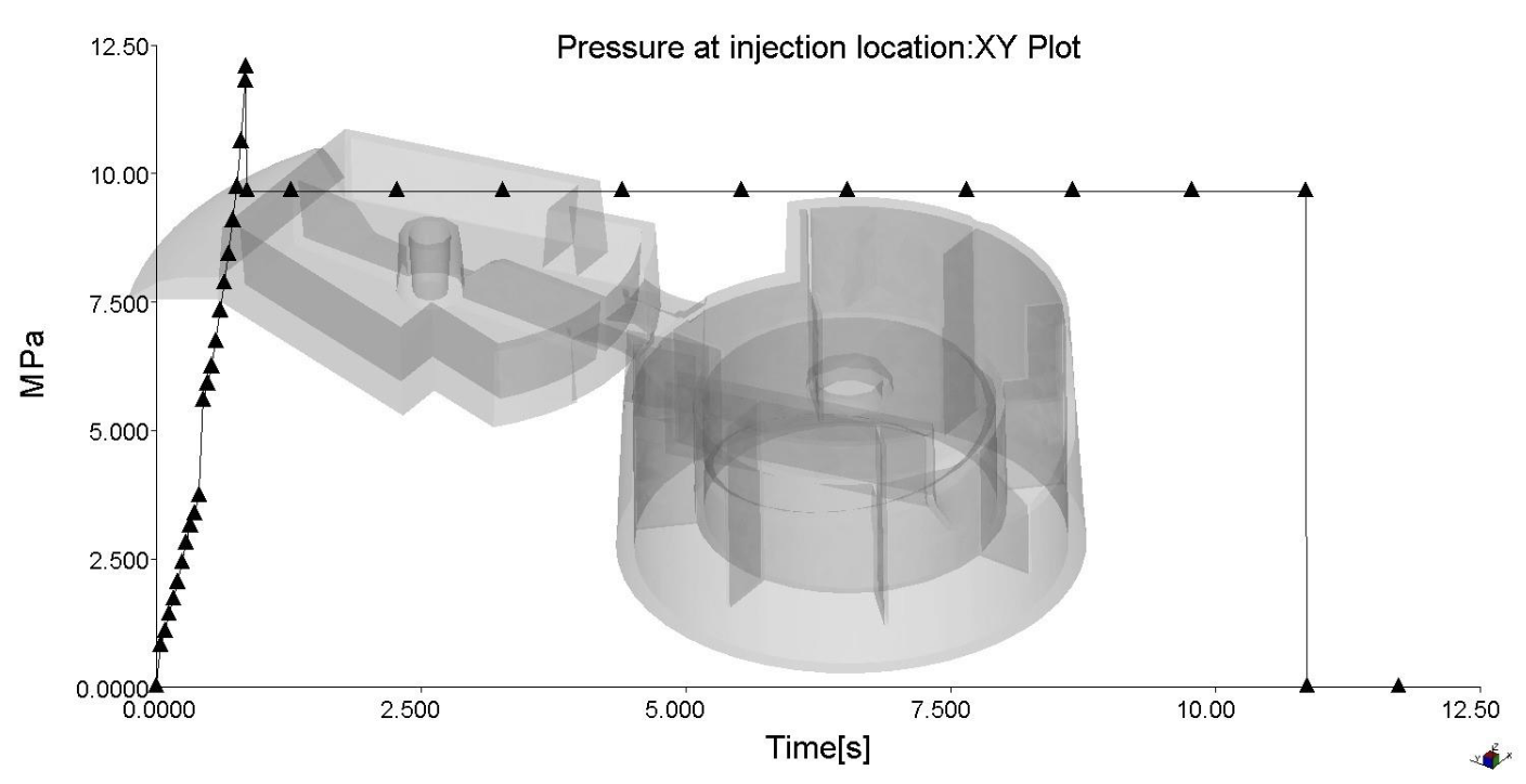
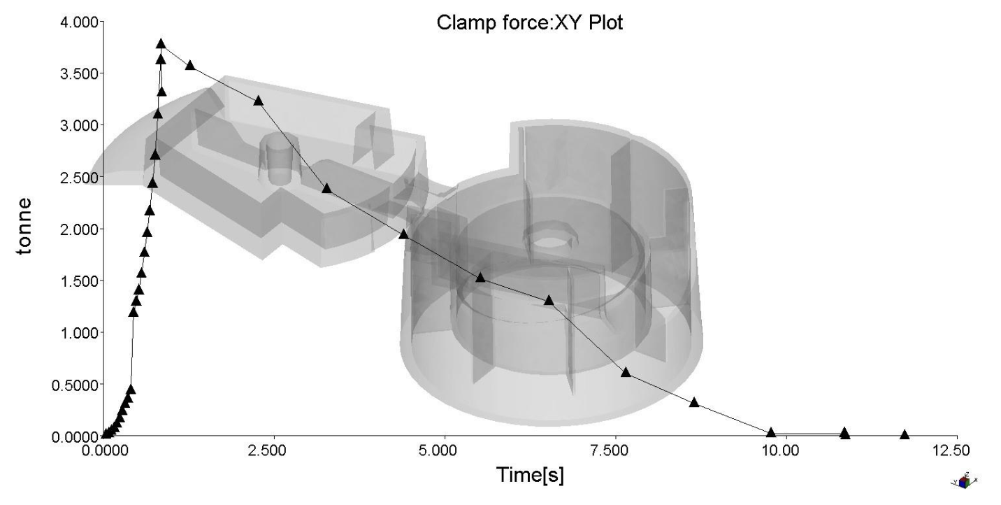
The clamp force and maximum injection pressures have also been optimized, with a maximum clamp force of ~3.8 tonnes and a maximum injection pressure of ~12.5 MPa.
Weld lines were inevitable due to the multiple injection locations, but mitigated. The weld lines were not found to be in critical locations.

Figure 9: Weld lines analysis
References
Huang, D. (2025). ME module 6 – specialization - Simulation of Injection Moulding (SIM) [PowerPoint slides]. Canvas@UTwente. https://canvas.utwente.nl/courses/17480/pages/sim-lectures?module_item_id=616131